|
the experiment shows,  The cold cracking tendency of Cr-1Mo steel is relatively large. With the increase of preheating temperature, the joint resistance to cold cracking is improved. When Tr ≥ 200 °C, the cold cracks are all eliminated. Therefore, the preheating temperature before welding is selected at about 200 °C to meet the crack resistance requirements. The cold cracking tendency of Cr-1Mo steel is relatively large. With the increase of preheating temperature, the joint resistance to cold cracking is improved. When Tr ≥ 200 °C, the cold cracks are all eliminated. Therefore, the preheating temperature before welding is selected at about 200 °C to meet the crack resistance requirements.
2.2 Welding line energy
It can be seen from the previous test that when the preheating temperature is 200 °C and the welding line energy E is about 10 kJ/cm, the weld seam does not crack, and the E value at this time should be the critical value (lower limit value). From the point of view of molding, under the specification, the root base and the second and third layers are transitioned, the full position is well formed, and the reverse surface height is also within the control index, while the other weld layer specifications are in the joint to obtain a good comprehensive mechanics. Under the premise of performance, you should choose as much as possible to improve production efficiency. Therefore, a line energy upper limit must be determined. Two options are used for this test: a 110 kJ/cm specification primer transition, a 20 kJ/cm gauge fill and a cover. 210 kJ/cm specification base transition, 30 kJ/cm gauge fill and cover. The samples of both solutions were tempered at 710 °C for 2 h. Check the normal temperature mechanical properties of the joint and the impact toughness at -50 °C. The joint tensile strength at room temperature is 570 ~ 580 MPa, and it does not crack after 90 ° cold bending. The comparison of the impact energy at -50 °C between the weld zone, the fusion zone and the heat affected zone of the welding specimens of the two schemes is shown in Fig. 1. Under the same heat treatment conditions, the reduction of the solder layer and the increase of the line energy result in a decrease in joint toughness. This is mainly because the cooling rate is slow after the increase of E, resulting in coarse grains in the superheated zone and poor toughness. Cr-1Mo steel has a strong tendency to temper embrittlement, which has a large loss of joint toughness. Therefore, in order not to excessively increase the plastic-brittle transition temperature by the increase of E, the toughness of the joint is lost, so 20 kJ/cm is selected as the upper limit of the welding specification. 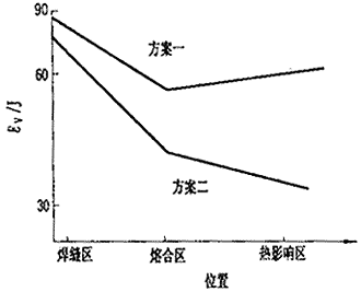
Figure 1 Effect of line energy on toughness 2.3 Post-weld heat treatment specification [1] pointed out that for Cr-Mo steel, the tempering parameter [P] varies from 20.0 to 20.6, but for a specific weldment, there is an optimum [P] value. . For wall thickness 27 mm After the post-weld heat treatment of Cr-1Mo furnace tube, the [P] value is taken as the lower limit of 20.0 and the heat preservation is for 2 h. According to the tempering parameter calculation formula, there are: [P]=T(20+lgt)×10-3 (1) Where T is the tempering temperature, K; t is the holding time, h. From the formula (1), T = 710 °C. In order to further understand the influence of the tempering specification on the joint performance, the welding samples of the above scheme 1 were tempered at 650 ° C, 710 ° C and 760 ° C for 2 h, and then the performance test was carried out.
In order to investigate the influence of [P] on the impact toughness of -50 °C, the V-notch impact test of -50 °C was performed on the heat affected zone of the sample at 650 °C, 710 °C and 760 °C. 2. 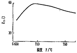
| Figure 2 Effect of heat treatment temperature on toughness 2.4 [P] Effect on weld strength The joint is subjected to room temperature stretching and 425 °C high temperature short-time tensile test. The results are shown in Table 3. The tempering parameter [P] is taken as 20.0, that is, the tempering temperature is 710 °C. It is more appropriate. Table 3 joint temperature and high temperature short-term performance
| | Tempering temperature / °C | Σs/σb at room temperature | Σs/σb at 425 °C | | 650 | 612/436 | 507/359 | | 710 | 540/411 | 485/308 | | 760 | 538/402 | 475/284 |
3 joint temper embrittlement sensitivity test
3.1 Weld metal correlation coefficient X, J coefficient is an important indicator to measure the tempering sensitivity of Cr-Mo steel. The literature [2] pointed out that in order to ensure a good resistance to temper embrittlement of the weld, the X coefficient of the weld metal is required to be less than 25×10-6, and the J factor is less than 200. To this end, chemical composition analysis was performed on elements closely related to temper embrittlement, and the results are shown in Table 4. Table 4 weld temper embrittlement sensitive element content%
| | element | Si | Mn | P | As | Sn | Sb | | content | 0.37 | 0.75 | 0.006 | 0.000 4 | 0.000 9 | 0.001 |
The data from the table can be obtained: X=(10P+5Sb+4Sn+As)0.01=0.000 008 (2) J=(Si+Mn)(P+Sn)10 000=84.5 (3) Both values are below the control index, indicating that the selected welding material is sufficient to meet the requirements of tempering and embrittlement resistance. 3.2 The temper embrittlement evaluation test evaluation method uses Socal No. 1 step cold curve [2], see Figure 3. By step cooling treatment, the material is stepped through the embrittlement temperature to cause accelerated embrittlement conditions, so that the material embrittlement amount is larger in a shorter time.
| 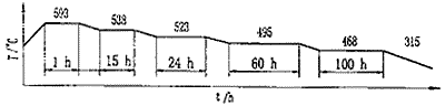
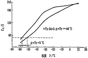
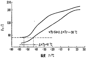
| Figure 3 step cooling treatment (SC) curve  The plastic-brittle transition temperature of temper embrittlement of Cr-1Mo material should meet the following requirements: The plastic-brittle transition temperature of temper embrittlement of Cr-1Mo material should meet the following requirements: vTr54+KΔvTr54≤38 °C (4) Where ΔvTr54=vTr'54-vTr54, vTr54 is the transition temperature at 54 J after the tempering treatment (SR); vTr54 is the tempering treatment plus step cooling treatment (SR+SC) after 54 J impact energy The transition temperature; K is the enhancement factor, which is taken as 2.0.
Welded samples with high temperature tempering (SR) at 710 °C for 2 h and tempered and then cold-treated (SR+SC) samples were used for welds and heat-affected zones at 20-60 °C. The notched impact test, the plastic-brittle transition temperature curve is shown in Figure 4 and Figure 5. It can be seen that the temperature of the impact energy of the weld and the heat-affected zone SR is -56 °C and -54 °C, and the temperature increment before and after the weld embrittlement is about 5 °C, so Tr54+2ΔvTr54=-46 °C, so the heat influence The temperature increment before and after the embrittlement is about 8 °C, then Tr54+2ΔvTr54=-38 °C, both of which are far below the control index.
| 
| Figure 4 Transition temperature curve before and after weld embrittlement
| 
| Fig.5 Transition temperature curve before and after embrittlement in heat affected zone
4 Conclusion
1 For thick fireplace tube welding, pre-weld preheating is necessary. When the preheating temperature is controlled at about 200 °C, cold cracking can be effectively prevented. 2 For the welding of the tube tube horizontally fixed and the obstacle position, the lower limit of the welding line energy is controlled at about 10 kJ/cm, and a satisfactory weld root formation can be obtained. For the filling bead and the cover surface, as the upper limit of the line energy increases, the weld layer decreases, the mechanical properties of the joint at room temperature change are not obvious, and the impact toughness at -50 °C shows a significant downward trend. In order to ensure reliable fracture toughness of the joint, the line energy control is suitable at 20 kJ/cm. 3 thick fireplace tube welded joints at room temperature and 425 °C high temperature short-term tensile strength, with the increase in tempering temperature have significantly decreased. The impact energy at -50 °C is shown at 710 °C, ie [P]=20.0. To ensure the comprehensive mechanical properties of the joint, the reasonable heat treatment specification is [P]=20.0, ie tempering temperature 710 °C, heat preservation 2 h. 4The TGS-2CM welding wire is selected, the embrittlement sensitivity coefficient of the weld is lower than the control index, the welding line energy is controlled at 10~20 kJ/cm, and the tempering parameter [P] is 20.0, the weld and heat affected zone The plastic-brittle transition temperature is low, the embrittlement temperature increment is small after the joint cooling treatment, the joint toughness is large, and the anti-tempering ability is strong. Therefore, the safety margin is large at high temperature, and brittle fracture does not occur.
About the author : Huang Yiluo (1969-), male, bachelor of engineering, welding engineer.
Author : Maoming Petrochemical Company, Maoming, Guangdong 525024, China references:
[1] Zeng Le. Handbook of Modern Welding Technology [M]. Shanghai: Shanghai Science and Technology Press, 1991.785-786.
[2] Qi Shubai. The technical collection of hot wall hydrogenation reactor manufacturing technology [C]. Beijing: Sinopec Beijing Planning Office, 1986.152. |
|


 September 06, 2021